Main menu
You are here
Oscillators & Filters
[last updated: 2023-04-21]
-----------------------------------------
BioAmp home page
filter trials...
oscillator trials...
...
-----
- Note:
- This investigation started when I needed some filters for the bioAmp project.
To start, I needed a 60-Hz notch filter for the bioAmp output,
then some narrow bandPass filters to do a hardware transform of EEG signal
into brainWave frequency slots. - then, in order to design and test various filters,
I needed a sweep-freq (ie. VCO) oscillator.
Such is the way projects expand...
----------------------------------------------------
- This investigation started when I needed some filters for the bioAmp project.
- Oscillators:
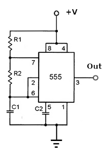
- 555 oscillators:
- Test 555 IC's
------------------------------- - Basic (2-resistor) astable:
- freqHz = ( 1.44 * 106 ) / ( ( R1 + ( 2 * R2 ) ) * Cuf )
- NOTE: "Duty cycle" is often defined as "mark/space ratio".
However I'm using the term in more intuitive sense of "% - high".tH-ms = 0.693 * (R1 + R2) * Cuf / 1000
tL-ms = 0.693 * R2 * Cuf / 1000D%-Hi = tH / (tH + tL)
- C2 nominal 0.01 uf
- C2 nominal 0.01 uf
- Basic (1-resistor) astable:

- not verified... f = 0.72 * R1 * Cuf
- Duty cycle nom 50%, though output load resistance will affect it.
- Note: as drawn, this circuit is set up for VCO operation with variable voltage into pin-5.
----------------------------------------------------
- VCO mod:
- Starting from the Basic-2R circuit above,
remove the 0.01 cap from pin 5,
connect a pot between +V and gnd,
with the wiper input to pin 5,
and the output freq will vary according to the pot setting. - Op-amp oscillators:
----------------------------------------------------
----------------------------------------------------
- Filters:
- Basic Filters:
-
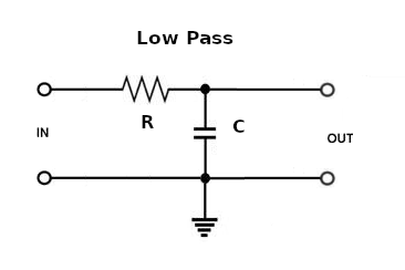
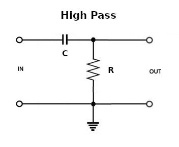
- Filter cutoff freq:
- fc = 1 / ( 2 * pi * R * C )
- A curiosity I don't yet have an answer for:
You could build a filter with eg. R = 1k and C = 1 uf,
and you could build another filter with R = 500 ohm and C = 2 uf
and they would both have the same cutoff freq, about 160 Hz,
but are there other consequences to changing component values like this?- Different bandwidth, ie. different Q
Q = (center freq) / bandwidth
----------------------------------------------------
-
- Twin-T Filters:
--------------------------------
- Notch Filter:
-
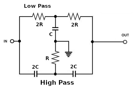
In this configuration, both the low-pass and high-pass filter sections
are tuned to the same freq, resulting in the "notch" that gets rejected/grounded. - Notch frequency:
- fN = 1 / ( 4 * pi * R * C)
-
----------------------------------------------------
- Basic Filters:
- Links:
.
.
.
.
eof